Photovoltaic power that exceeds instant self-consumption is typically fed into the grid and sold at only 0.05 € / kWh. This price is quite low, and it is what costs 1 kWh of heat produced with a gas or diesel boiler.
So I built a system that automatically turns On and adjusts the power of an electric heater, to heat up the house during the day by taking advantage of the photovoltaic over-production. The thermal inertia of the house brings the heat supplied by the heater from day to night. This translates into greater comfort and lower fuel consumption in the evening.

The control system
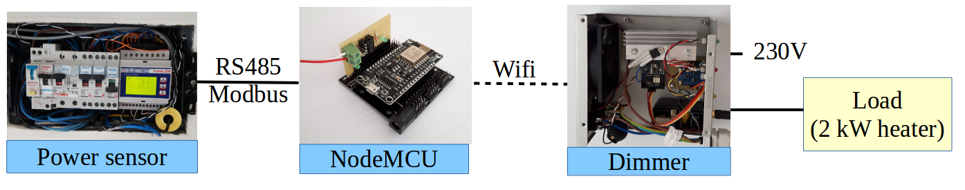
By use of two current transformers, the multifunction multimeter measures the power produced by the photovoltaic plant, and the power consumed by the home (including smart load).
An electronic card with NodeMCU processor programmed in C interrogates the multimeter via the RS485 interface, modbus RTU protocol, every 0.5s, and calculates the power value exchanged with the network as P_exch = P_Load–P_Production.
The ESP8266 card does three things:
- sends every 10 seconds to the remote MySQL server for remote recording and monitoring.
- provides the main data on a graphical web interface accessible locally. The page is a “single page application” programmed in HTM, CSS and AJAX, which queries the card via HTTP every 1s to update the values on the page.
- Responds to the HTTP requests of the dimmer board with the power value exchanged with the network (positive if in withdrawal, negative if in input).
The dimmer board is also based on an ESP8266 processor which interrogates the first board with a frequency of 2Hz, and controls the stove with the phase partitioning technique.
The dimmer board reads the passage of the mains voltage to zero, and triggers the triac with a delay of between 0 and 10 milliseconds, to adjust the power to the heater.
All software is implemented using Ubuntu and free open-source software.
The control loop
The control technique implemented at the moment is a proportional regulator, where the error is the power exchanged with the network. If positive there is picking, and the load is progressively reduced by an amount proportional to the error. The dimm variable retains the value of the regulating action from one iteration to the next. The regulation loop is updated with a frequency of 2 Hz.
eq1) AzProp = Kp * P_grid
eq2) dimm = dimm-AzProp
dimm is dimensionless, from 0 to 10 thousand represents 0-100% of ignition of the load. Consequently, the proportional coefficient Kp is dimensionally 1 / W.
kp = 0.15 W ^ -1
To avoid too strong regulator actions and system instability, a saturation of the AzProp action is inserted. | AzProp | <500.
Test run
When the dimmer is turned on, it interrogates the measurement card and, finding a negative exchanged power (feeding into the grid), it starts to increase the power absorbed by the heater. Consequently, the power fed into the grid decreases down to zero. When another load is turned on in the home, the grid exchange becomes positive (draw), the power to the heater is progressively reduced until the new balance is found between production and consumption.

