This circuit can be used to simulate a PV panel up to 30W and 40V.
The open circuit voltage depends on the supply voltage. The short circuit current is tuned using the variable resistor VR1.
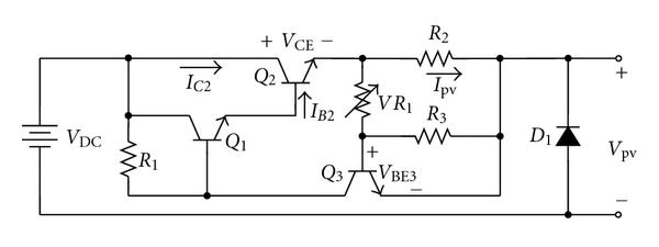
At the start, R1 feeds current to the base of Q1, which feeds current to the base of Q2, who lets the current flow from collector to emitter, then trough R2 and the load.
When the circuit load increases, the voltage across R2 increases. This voltage (positive at the side where the current enter R2) is divided by the VR1 and R3 voltage divider, and it is applied to the base of Q3.
When Vbe3 exceeds 0.7V, the transistor Q3 starts to drain current away from the base of Q1. Progressively, the transistor Q2 receives less base current and let pass less current from the collector to the emitter. A collector emitter voltage appears, and Q2 dissipates the power that is not provided to the output.
This is why this circuit can only be used up to a few tens watt.
For a larger power, see my solution that uses a mosfet and PWM.
I haven’t built this circuit but to simulate a 30V 30W PV module I would use the following components:
- Q2: 2n3055 (60V 15A) + heatsink (or TIP35C, 25A 100V)
- Q1, Q3: BC337 (800 mA 45V), or 2n2222 (600mA 60V)
- VR1: 1 kOhm trimmer + 220 ohm resistor in series
- R3: 1 kOhm
- R2: 2 Ohm 5 W
- R1: 1 kOhm