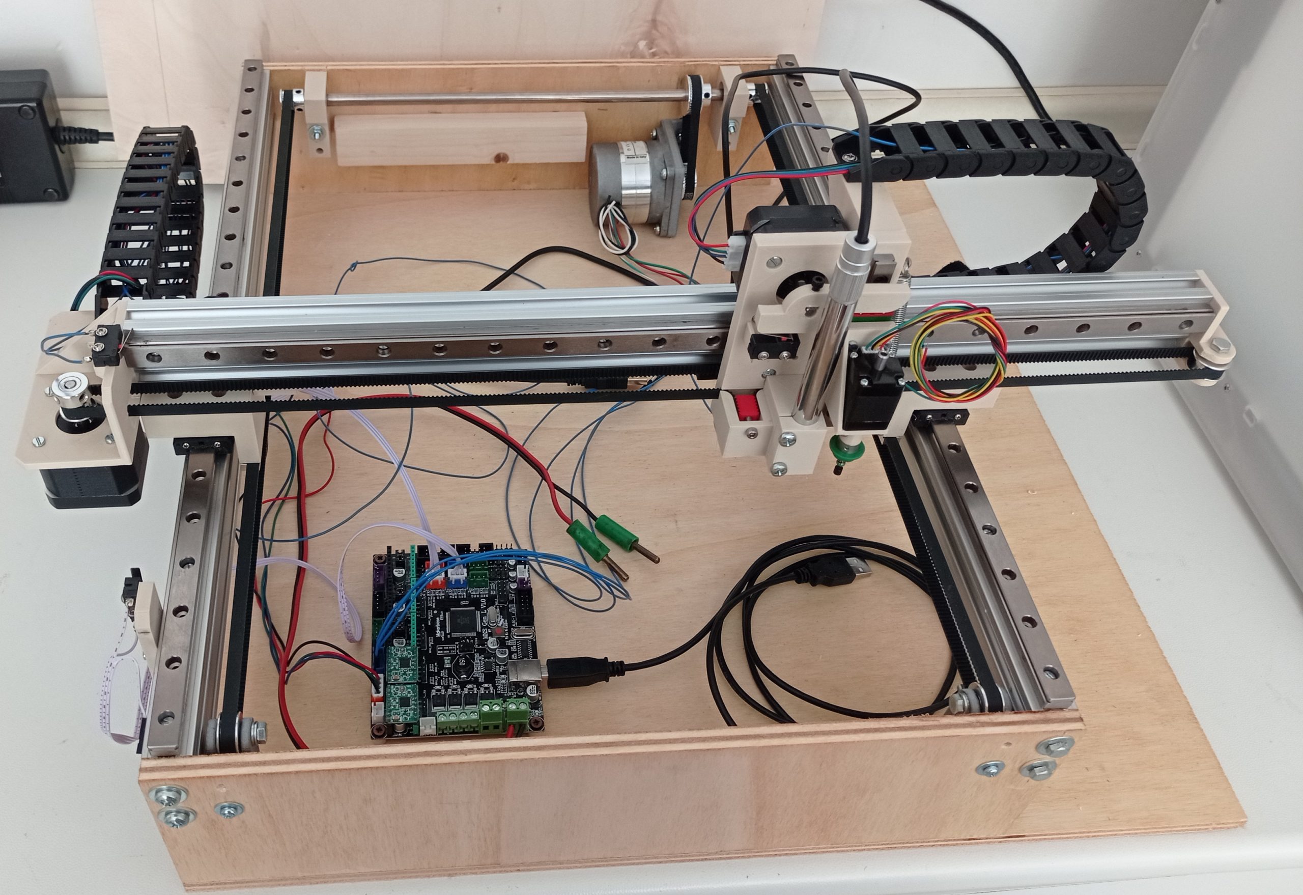
This PnP machine is designed to be precise (linear rails) and economic (small 3D printed parts, wooden frame), and use of narrow motorised feeders of a novel concept: one servo -> two feeders -> autofeed. As the machine has 4 motors (X, Y, Z, nozzle rotation) I am basically using a control board meant for 3D printers. The output meant for the heated nozzle will command the vacuum pump to pick up the components.
This are my notes on what I did and what I plan to do, as the machine build is ongoing.
- Software on the PC: OpenPnp
- Control board: MKS-GEN-L + A4988
- Software on the control board: Marlin 2
- Top camera: USB microscope Andonstar ZN528600
- Bottom camera: USB webcam.

Hardware parts
- 3x 500 mm aluminium extrusions 20×40 mm.
- 3x linear rail 500 mm MGN12, and one rail 100 mm MGN9 for the nozzle up-down.
- Stepper motors: Nema 17 (X and Z), Nema 23 (Y), Nema 8 (nozzle)
- GT2 Timing belt (in 5 m roll)
- T-nuts M3 and M4.
- Various length M3 screws (6-8-10-12 mm), a few M4 and M6 screws. Four M2x8 mm screw for the Nema8 motor.
- 8 mm shaft, with two small and one large pulley.
- 4 mm small pulley + 3 free spinning pulleys 4 mm.
- Cable chain 2x 1m
Head
The head carries one nozzle, and a USB microscope from Andonstar. The microscope has Leds itself, therefore there is no need for more. I will not use drag feeders, therefore there is no prick on the head. The prick is a system that does not work well with thin plastic tapes, because as the needle moves and hit the tape, the small components like 0805 Leds will jump out of the tape.
The nozzle is pushed down by the stepper motor, and pulled up by a spring. This allows you to push the nozzle down by hand, which is extremely useful for example to configure pick-up locations.
In principle you could put a second nozzle, but I decided to keep it simple to start with. A 504 Juki nozzle can surprisingly pick up quite large parts like SMD buttons, and 12×12 mm chips.
Feeders
I want the feeder to be narrow and simple. The idea is to use a single SG9 servo motor to actuate two feed lines with a “dog” system. The connection to OpenPnP works using a second USB port on the PC and an Arduino that will receive serial commands from OpenPnP, and will actuate the feeders mechanisms. I will use one pin for two feeder lines.
The drag feeder method in my opinion is a pain, as it is unreliable on thin plastic tapes carrying small components (that jump out of place when the needle hit the tape).

Tapes containing small parts that might not like the vibrations, could be made with a motor pulling the tape. Thin plastic tape is not good to push, need to be pulled.
The switch could be used to tell the feeder controller to feed, that makes the feeder usable on machines not running OpenPnP.
The cover tape will be pulled back using weights, maybe.
Coordinate system
Our origin is the bottom left corner. X goes to the right. Y goes away from you. Z goes up.
Connections to main board
What matters to us are the motors, the limit switches on the left column, the Power in and USB port.
Install the stepper motor driver. I used A4988 and let all the jumpers in, that makes 1/16 microstepping.

First motor run from serial commands in G-code
Connect X motor and one limit switch ( to connector X-) to the main board. The limit switch connector on the mainboard has 3 pins, V G S, which stands for Voltage, Ground, Signal. You need to connect a NC contact between Ground and Signal.
M119 X will test the limit switches position.
Open Arduino IDE, download Marlin 2, set the target board to Arduino Mega 2560, flash the firmware (it will take long to compile). Open the serial monitor. When the board boots you should see the configuration of the board printed out.
Enable the motors with M17 (the EN line goes low).
Send G0 X10 F100 to move the X motor 10 mm with feedrate 100. If it works, move onto OpenPnP.
If it doesn’t, check the motor connections (I had a JST connector wired different than the stepper driver), check the Step line with the oscilloscope.
If the motor turn in reverse, swap the wires of one winding by pulling the plugs from the JST connector.
First motor run from OpenPnP
How OpenPnp works: it basically sends G-code commands to the mainboard. The rules that define what G-codes to send is called “the driver” and can be easily customised.
For example, in Machine setup -> driver ->Gcode driver->Gcode->Settings->HOME COMMAND I have
“G28 ; Home all axes”, but I will add before this line a command to set the steps/mm to the correct value “M92 X80 Y80 Z80” https://marlinfw.org/docs/gcode/M092.html
Setup OpenPnp https://github.com/openpnp/openpnp/wiki/Setup-and-Calibration
Limit switches and homing
One switch in the negative travel direction is enough to start with (see the OpenPnp coordinate system), as the positive direction can use a software limit switch. OpenPnP will need to home the machine (move all the axis to the limit switch) at the beginning.
To test the status of the limit switches using the serial monitor write M119 command.
G28 X to make the machine home the X axis.
Before issuing the command it is very important that your motor is turning in the correct direction, and the limit switch works. Otherwise you will crash the axis. I suggest that you keep your hand close to the power off switch shall something go wrong.
G28 Y to home the Y axis.
To be continued…