 First of all, these motors have two speeds and the various connections serve to select the speed and reverse the direction of rotation. As they are hybrid asynchronous devices, they use a capacitor connected in series to one of the windings.
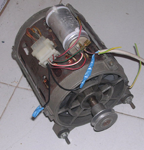
You have to find amongst the five wires the commonplace of all. If the terminal board is with the online terminals it should be the first, if they are on two files (usually a 3 × 2 faston connector with an empty hole) the common one is alone.
When you have identified the probable common measure with the tester the resistance between this and the other 4 terminals (one at a time of course). You should find four values ??similar to two to two. Let me explain better: we number the terminals 1 to 5 and suppose number 1 looks like the common one. Between terminals 1-2 and terminals 1-3 find a similar resistance value (say 10 to 15 ohms) and between the terminals 1-4 and 1-5 another higher value (30 to 50 ohms).
The two lower resistance clamps are those of the highest speed, those with the highest resistance are of low speed.
Decide how to use the motor (high or low speed) and consider only the two corresponding terminals (those with equal resistance to the common) and the common one.
Connect the ignition capacitor between the two terminals (leave the joint free) and feed the motor by connecting it to the common terminal and to one of the terminals to which the capacitor is connected (one or the other determines the direction of rotation).
The capacitor should have a value between 10 and 20 microfarad, but you should try different values.
All clear?
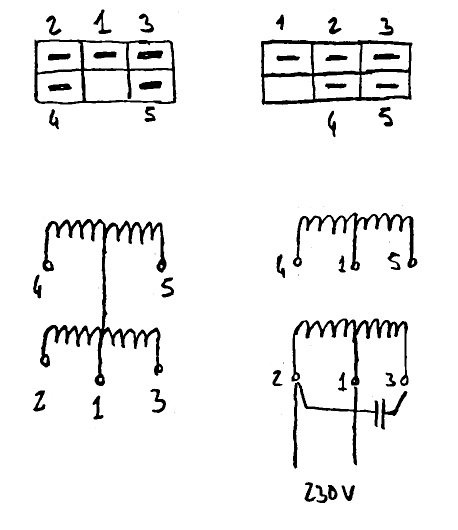 Usually the washing machines have 2 pairs of windings (one for the centrifuge and one for the slow rotation). In the example here below, the 3 terminals above were used for slow rotation and 3 for centrifuge. The capacitor must be connected between the two windings marking similar values ??to the center terminal.
In some cases the thing is different because they spared a terminal, connecting the two wires of the center of the two armatures together, in this case all the wires indicates resistance between them and it is more difficult to identify the coils.
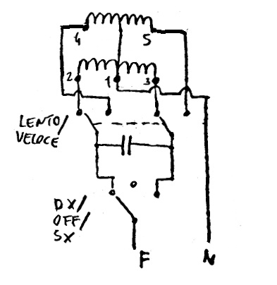
In the diagram below, a diverter is used to choose the winding (= speed) to be used. The center zero diverter is used to choose which side to power the condenser, ie to choose the direction of rotation. The center zero position is used to prevent the engine from starting in the opposite direction to the drive.
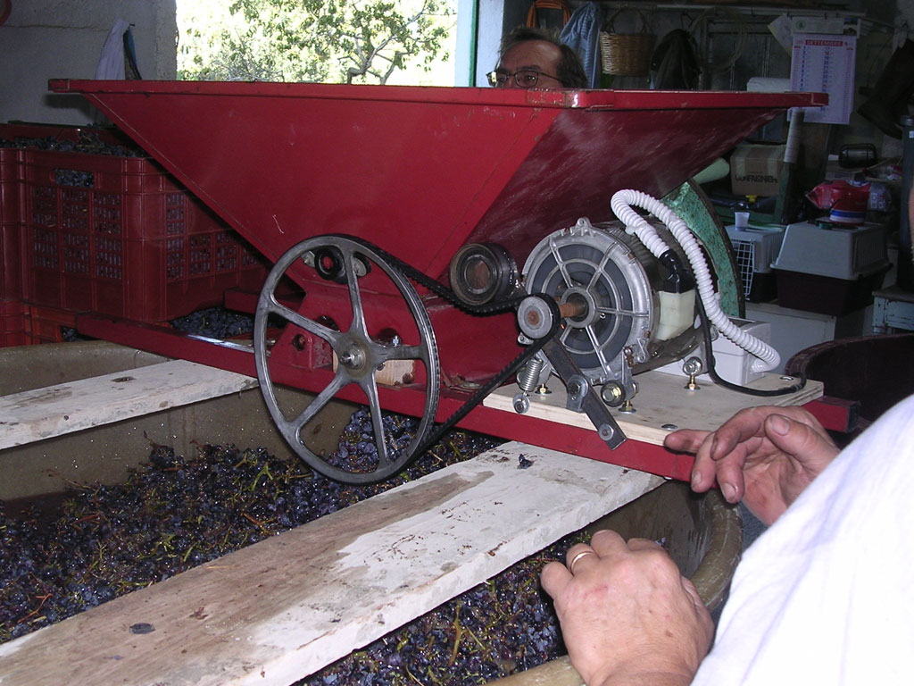
An application of a washing machine, to operate a grain mill.